Difference between revisions of "PIC based Stepper Motor Dancing Analog Clock"
Russ hensel (talk | contribs) |
Russ hensel (talk | contribs) |
||
| Line 112: | Line 112: | ||
Single sided, for toner transfer, in Eagle ( semi-final, less ground plane, files may be more up to date ) | Single sided, for toner transfer, in Eagle ( semi-final, less ground plane, files may be more up to date ) | ||
| + | Note that I have included some parts for very conserative design, which I did not in fact use. | ||
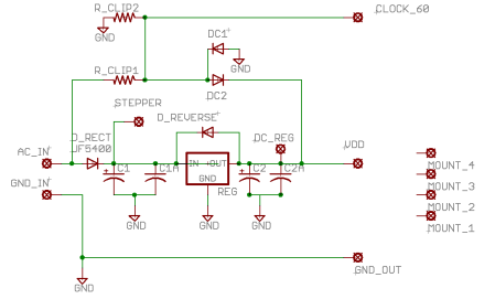
| − | [[PowerSupplyBoardSch.png | Power Supply Schematic | + | [[Image:PowerSupplyBoardSch.png | Power Supply Schematic ]] |
| − | |||
| − | |||
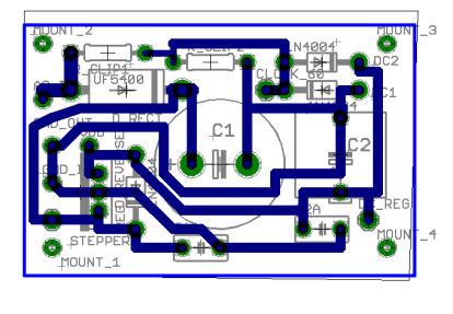
| + | [[Image:PowerSupplyBoardBrd.png | Power Supply Board ]] | ||
Parts | Parts | ||
| Line 131: | Line 131: | ||
|-valign="top" | |-valign="top" | ||
| − | |Rectifier Diode | + | |D_RECT = Rectifier Diode |
| − | | | + | |Size for current needed by motors, then say double. Let the reverse voltage be 4 x the input voltage. Mine came from salvage. Look on Instructables.com for similar power supplies. |
<!--------------------------------> | <!--------------------------------> | ||
|-valign="top" | |-valign="top" | ||
| − | |Filter | + | |C1 = Filter Cap |
| − | | | + | |My junk box yeilded 4,700 mfd at 25 volts |
<!--------------------------------> | <!--------------------------------> | ||
|-valign="top" | |-valign="top" | ||
| − | |High Frequency Bypass | + | |C1A = High Frequency Bypass |
| + | |.01 to 1 mfd cap with good high frequency response, mica is fine. Electrolytic to be avoided. | ||
| + | <!--------------------------------> | ||
| + | |-valign="top" | ||
| + | |C2 = Filter Cap | ||
| + | |Probably can skip, I did. | ||
| + | <!--------------------------------> | ||
| + | |-valign="top" | ||
| + | |C2A = High Frequency Bypass | ||
| + | |.01 to 1 mfd cap with good high frequency response, mica is fine. Electrolytic to be avoided. | ||
| + | <!--------------------------------> | ||
| + | |-valign="top" | ||
| + | |DC1, DC2 = Clipping Diodes | ||
| + | |Clip the AC for the time keeping to +5 and 0 volts. Protects the input of the PIC. | ||
| + | <!--------------------------------> | ||
| + | |-valign="top" | ||
| + | |R_CLIP1 R_CLIP2 = Clipping Resistors | ||
| + | |10 k resistors, form voltage divider to the timing signal to PIC, limits current to DC1 and DC2. | ||
| + | <!-------------------------------- | ||
| + | |-valign="top" | ||
| + | |x | ||
| | | | ||
| + | <!-------------------------------- | ||
| + | |-valign="top" | ||
| + | |D_REVERSE = reverse voltage protection diode | ||
| + | |Use only if you worry about reverse voltage protection on the regulator. Not real likely, I left it out. | ||
<!--------------------------------> | <!--------------------------------> | ||
|-valign="top" | |-valign="top" | ||
| − | | | + | |D_REVERSE = reverse voltage protection diode |
| − | | | + | |Use only if you worry about reverse voltage protection on the regulator. Not real likely, I left it out. |
| + | <!--------------------------------> | ||
<!-------------------------------- | <!-------------------------------- | ||
|-valign="top" | |-valign="top" | ||
| Line 155: | Line 180: | ||
|x | |x | ||
| | | | ||
| − | |||
| − | |||
| − | |||
|} | |} | ||
Revision as of 15:35, 1 October 2008
Contents
Summary
- Name: PIC based Stepper Motor Analog Clock with Dancing Hands
- Purpose: An amusing analog clock, see below.
- Status: This is a very early draft. Code works but still in refinement, code available, email russ_hensel
- Technology: Stepper Motors, PIC 16F877A and BoostC
- Author: russ_hensel ( where you can find an email address to reach me )
- License: Open source and object code.
This is an analog clock, with real hands driven by stepper motors. Because stepper motors are quite powerful the clock could be made quite large, 3 feet in diameter is probably within reach still using inexpensive ( salvage ) stepper motors. The project description includes eagle files for the circuits and a BoostC project with source code for the PIC.
Major Parts
- 2 Stepper Motors -- probably can be salvaged from printers or 5 1/4 disk drives ( where I got mine )
- PIC16F877 processor -- Others can be used, but this guy has a lot of IO, quite a bit is used for the clock
- Low sid Driver Chip -- but any transistors with reasonable beta and enough current handling capacity could be substuited.
- Case -- With a bit more work than I have done you could have a really nice case. I am working on an oak one now
- Clock Face -- Some good artwork here could make a really good looking clock, anyone willing to send me an high quality graphics file?
- Circuit Board -- Right now mine is built mostly on a proto board, but I have designed but not tested printed circuit boards suitable for single sided, toner transfer, fabrication.
Features
| Feature | Details |
| Hour hand/ Minute Hand | Hour hand is of conventional layout, but only changes hour on the hour. The minute hand is more like an elevator floor indicator, rotates 180 degrees, moves to the next minute on the minute. |
| Special effects -- Dancing | Hour and minute hands may "dance" at special times, see the video at: xxx |
| Power / timekeeping | Powered from outlets, timekeeping based on the powerline ( which is long term very accurate (( less power outages )) ). |
| Optional Serial Interface | For debugging and demo of special effects
|
Circuit
The circuit does not need much explanation beyond the schematic and parts list. Here is just an overview.
To make it really easy to fabricate the printed circuit boards I seperated the power supply from the processor board.
Power Supply
This is a straight forward half wave rectifier with a linear regulator. It is powered by a wall wart transformer rated at about 9 volts. The unregulated voltage is over 9 volts ( 9 * ( 2 ^ 1/2 )) by simple theory. This unregulated voltage is used directly by the steppers so choose you wall wart to match your stepper motors. You should also size the filter caps based on the current that will be used by the motors. A couple of volts of ripple is not a problem as long as you have enough overhead for the 5 volt regulator ( the PIC might run on less, let me know if you try it ). An important part of the power supply is a 60 hz, roughly square wave. It is clipped off from the AC input. The 60 Hz power line tends to be very accurate over the long term, less so if you suffer power outages. You could run the clock on DC but the motors load down a battery pretty badly and you would need a timing signal ( the original code has a subroutine for timing off the crystal ).
Power Supply Schematic and Board
Single sided, for toner transfer, in Eagle ( semi-final, less ground plane, files may be more up to date ) Note that I have included some parts for very conserative design, which I did not in fact use.
Parts
| Part | Details |
| Wall Wart | You need one with AC output to get the 60 Hz timing signal from the power line. Mine is a 9 v 800 ma unit. I found it somewhere. |
| D_RECT = Rectifier Diode | Size for current needed by motors, then say double. Let the reverse voltage be 4 x the input voltage. Mine came from salvage. Look on Instructables.com for similar power supplies. |
| C1 = Filter Cap | My junk box yeilded 4,700 mfd at 25 volts |
| C1A = High Frequency Bypass | .01 to 1 mfd cap with good high frequency response, mica is fine. Electrolytic to be avoided. |
| C2 = Filter Cap | Probably can skip, I did. |
| C2A = High Frequency Bypass | .01 to 1 mfd cap with good high frequency response, mica is fine. Electrolytic to be avoided. |
| DC1, DC2 = Clipping Diodes | Clip the AC for the time keeping to +5 and 0 volts. Protects the input of the PIC. |
| R_CLIP1 R_CLIP2 = Clipping Resistors | 10 k resistors, form voltage divider to the timing signal to PIC, limits current to DC1 and DC2. |
| D_REVERSE = reverse voltage protection diode | Use only if you worry about reverse voltage protection on the regulator. Not real likely, I left it out. |
| PIC16F877A | |
| Low Side Switch | |
| Rotery Switch | |
| Single Pole double throw Momentry Switch | |
| Pull Up/Down Resistors |
|
Program
Nothing very fancy here. The 60 Hz input is fed to the port x interrupt. This lets the PIC keep time. The hands are not moved during the interrupt instead flags requesting hand movement are set and the main loop moves the hands.
Invalid states for the mode can easily happen with a rotory switch when the wiper is not fully in position. Because of this not all possible states on the mode input are used.
The stepper control is half step. The activation of the coils is determined by an array which hold the 8 different activations of the coils.
For the serial interface code see Serial Communications Library -- BoostC and 16F877A
Additional Ideas
- Add a chime perhaps using an D to A converter and small amp and speaker.
- Add an LED to show the clock is powered or running, make blink at 1 hz if that pleases you ( I do not like the blink ).
- Work on more dances.
- The mode control is based on inputs that are pulled down, the chip has an option for weak pull up on the port, using this and pulling down with the mode switch would get rid of a bunch of resistors on the board.
- Add battery backup to keep the internal time ( but not the hands ) running during a black out.
- Make it really big.
Download
Comming, email me until then see [[russ_hensel]
Comment, Questions, Contributions?
Email me russ_hensel, or use the talk page for this topic. All feedback is welcome.

