Difference between revisions of "Minimig Board v1.0 schematic"
Jump to navigation
Jump to search


(layout fixed) |
(4bit dac, video output mode notes) |
||
| Line 7: | Line 7: | ||
[[Image:Minimig_v10_board_dac.png|thumb|right|250px|4 bit resistor ladder D/A]] | [[Image:Minimig_v10_board_dac.png|thumb|right|250px|4 bit resistor ladder D/A]] | ||
Notice the resistor of 560 ohm. May cause inlinear output.<br> | Notice the resistor of 560 ohm. May cause inlinear output.<br> | ||
| + | :in 15kHz mode: | ||
| + | :/VSYNC = high (scart RGB enable) | ||
| + | :/HSYNC = composite sync | ||
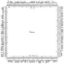
[[Image:Minimig_v10_board_fpga.png|thumb|right|250px|[[FPGA]] Xilinx XC3S400-4PQ208C]] | [[Image:Minimig_v10_board_fpga.png|thumb|right|250px|[[FPGA]] Xilinx XC3S400-4PQ208C]] | ||
Revision as of 21:26, 2 August 2007
Board schematic for Minimig board v1.0

Voltage level: (3.3V/(560ohm + 560ohm + 32ohm))*32 ohm*1000 = 91,7mV
Back EMF issues?
Head phones

Notice the resistor of 560 ohm. May cause inlinear output.
- in 15kHz mode:
- /VSYNC = high (scart RGB enable)
- /HSYNC = composite sync

FPGA Xilinx XC3S400-4PQ208C

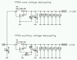
FPGA core power +1,25V +2,5V using LM1117MP-ADJ

FPGA decoupling


MC68000 Decoupling

PATCH needed to get rev 1 board working:
- Disconnect net SPI_DOUT from pin 81 of FPGA.
- Connect net SPI_DOUT to pin 19 of FPGA (net USER3).
- REASON:
- Pin 81 is an output during FPGA config that blocks SPI to MMC during startup.


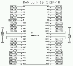
Asynchronous static ram 512 x 16 bit (2 chips)


SD Card slot
